A set of geometry node modifiers used for procedurally generating supports for resin 3D-printable models, with accompanying python tools and also including materials for layer visualization.
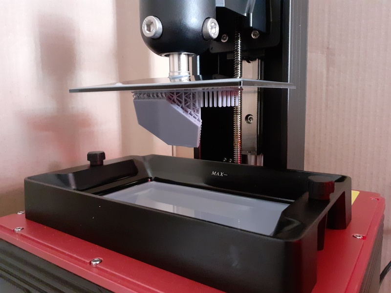
In resin 3D-printing, models are printed upside-down stuck to a "build plate" that advance upwards for each layer that is "added" to the print.
Supports are required in order for the print to come out intact and are designed in a way as to be easily removable from the actual model with minor cleanup.
The main problems that supports address:
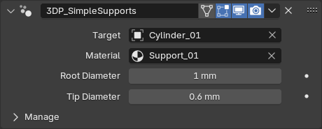
The input geometry acts as an interface for defining the structure of the supports.
The resulting shapes are mainly parameter driven.
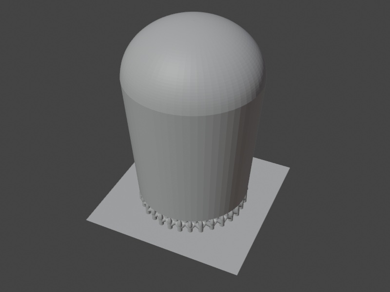
"Rafts" are platforms that attach directly to the build plate and from which everything else emerge.
In order for the print to properly stick to the build plate, the initial "burn-in" layers are hardened for a longer time wich will result in them swelling, and for this reason models are usually suspended from the build plate as to not be part of those layers.
This modifier simply extrudes polygons and slants the border faces inwards wich is required for safe removal of the print from the build plate.

For when you need to suspend large horizontal surfaces, like the base of a miniature.
Edges that emerge from vertices at the "zero level" will form tips that automatically will make contact with the nearest surface point of the model.
The primary modifier of the set. It handles most use cases which usually requires a complex structure for durability and being able to reach obscure areas.
Below follows a breakdown of the various "components" that this modifier generates.
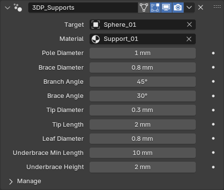
The core component is the pole from which all other components emerge.
They are formed by any "ground vertex" that makes at least one edge with another vertex above.
Poles are always vertical, positioned at the ground vertex and will by default break off into a branch followed by a tip.
The initial position of the tip is that of the above vertex and will automatically reposition and align itself to the closest surface point of the model.
Branches always have a fixed angle since it plays a major factor in durability.
Each edge that connects to a ground vertex will form a branch, sharing the same pole.
Edges coming out of the end vertex of a "branch edge" will form sub-branches called leaves.
The leaf farthest from the ground vertex will be promoted to a branch. Leaves will line up along the branch, maintaining maximum verticality.
Edges coming out of "leaf edges" will instead form a second level branch with it's own leaves. This branch will attach to the first level branch in the same manner as leaves.
Connected ground vertices will form braces between their poles. These are fundamental in forming a rigid support structure.
Braces, like branches, have a fixed angle, for the same reasons.
Ground vertices that to not produce poles but are connected with other pole vertices will also form poles and brace with their neighbours.
For when you need additional bracing without adding branches.
Branches that are long enough will form a bracing structure beneath them. As with regular braces, the angle is fixed.
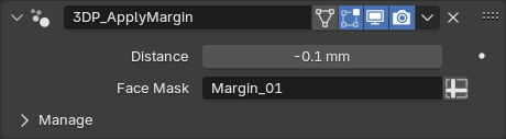
Displaces masked faces by some distance, maintaining the original shape. Used for tolerance adjustments in male/female parts of model assemblies.


Duplicates the selected vertices, connected to the same vertices as the originals.
Creates an edge between the active vertex and other selected vertices, optionally removing any existing connections.
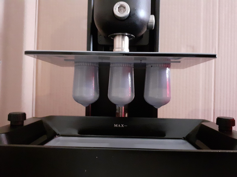
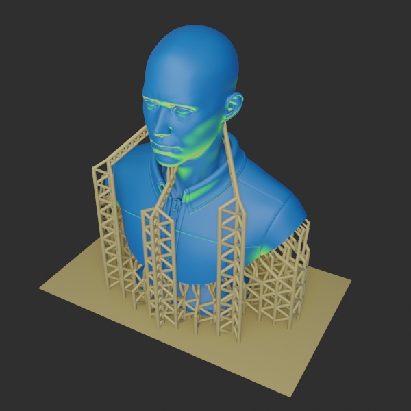
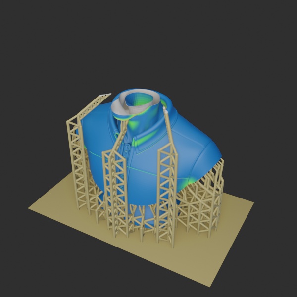
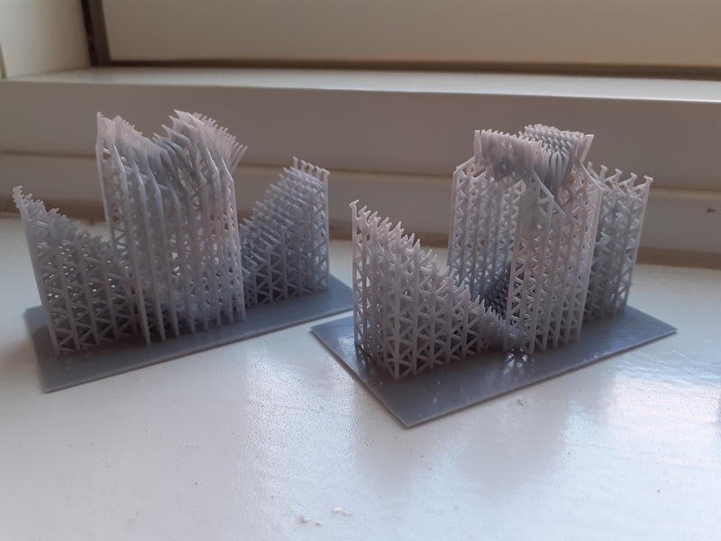
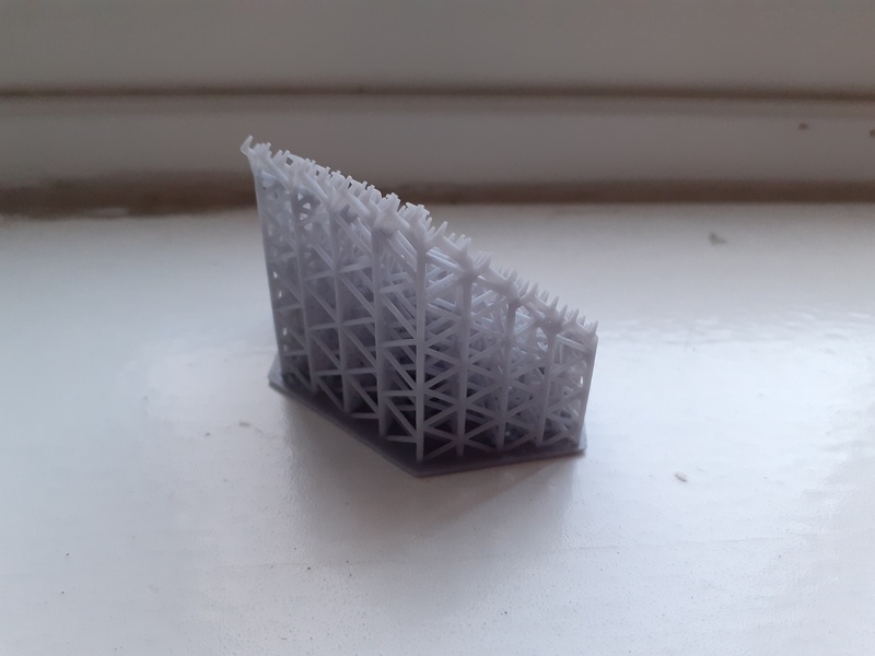
Test prints show that the generated supports satisfy the above mentioned requirements and are ready for use in advanced projects.
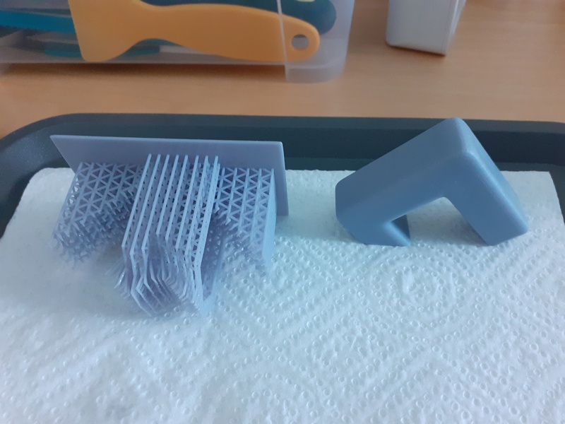
This test never succeeded as the underside of the top part was hard to reach, resulting in longer branches that remained too flexible. However this was mainly a stress test as the model was overly massive.


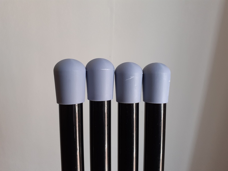
Another test, printing a leaning platform, as part of prototyping for a project. No issues here.

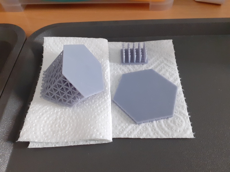

No pictures of the printed supports as they had to be broken during removal.